Use this information to install an optical drive.
The following notes describe the type of drives that the server supports and other information that you must consider when you install a drive. For a list of supported drives, see the Lenovo ServerProven website.
- You can go to Front view to see the locations of an optical drive on the server.
- Locate the documentation that comes with the drive and follow those instructions in addition to the instructions in this chapter.
- Make sure that you have all the cables and other equipment that are specified in the documentation that comes with the drive.
- The server supports one ultra-slim SATA optical drive.
Note: The optical drive is available only on some models.
To install an optional optical drive, complete the following steps:
- Remove the retention clip from the side of the optical
drive filler panel. Save the optical drive filler panel for future
use.
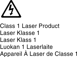
Note: If you are installing an optical drive that contains a laser, observe the following safety precautions.
Statement 3
 CAUTION:When laser products (such as CD-ROMs, optical drives, fiber optic devices, or transmitters) are installed, note the following:
- Do not remove the covers. Removing the covers of the laser product could result in exposure to hazardous laser radiation. There are no serviceable parts inside the device.
- Use of controls or adjustments or performance of procedures other than those specified herein might result in hazardous radiation exposure.
DANGERSome laser products contain an embedded Class 3A or Class 3B laser diode. Note the following.Laser radiation when open. Do not stare into the beam, do not view directly with optical instruments, and avoid direct exposure to the beam.
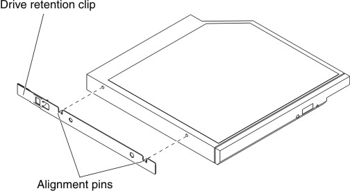
- Attach the drive retention clip that you removed from the
optical drive filler panel to the side of the new optical drive.
Figure 1. Optical drive retention clip installation
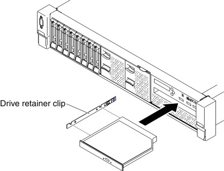
- Align the optical drive in the drive bay and slide the
optical drive into the optical drive bay until the optical drive clicks
into place.
Figure 2. Optical drive installation